


Industrial DAQ System - iDAQ Series
Advantech's Modular DAQ System
In the initial phase of a project, test engineers frequently face the crucial decision of selecting the appropriate DAQ core platform. This choice is pivotal, as it influences not only the project's current scope but also its future expansion. Essential technical parameters such as the number of channels, sampling rate, compatibility with sensor types, and the spatial logistics between the DAQ unit and the measurement site are critical considerations. Equally important are factors like the total cost of ownership, including hardware expenses and development time.
The chosen system should not only meet the project's immediate needs but also offer the flexibility to adapt to future requirements. This consultative approach can significantly enhance the project's success by ensuring a perfect match between the DAQ system's capabilities and the project's objectives. For industries such as production, automotive testing, environmental monitoring, and research and development, the capacity for rapid customization to meet specific test requirements is a critical advantage. The modular Data Acquisition (DAQ) system from Advantech, known as iDAQ, epitomizes this capability. Its design allows for effortless addition or removal of modules, enabling the system to be tailored for various applications based on immediate needs. This versatility is particularly beneficial in dynamic testing environments where requirements can shift frequently.
The scalable architecture of Advantech's modular iDAQ systems ensures they can expand in tandem with evolving testing demands, obviating the need for completely new configurations. This adaptability not only conserves time and resources but also significantly speeds up the development cycle. By investing in a modular iDAQ system, organizations can ensure their testing infrastructure is not just a tool for today’s challenges but a long-term asset capable of adapting to tomorrow’s demands.
At the initial stage, the choice depending on the planned computing power and the location of the data acquisition system is of paramount importance.
Advantech offers two approaches to solving such problems:
1. Combination of an industrial computer with 4 or 8-slot chassis such as iDAQ-934 or iDAQ-938 connected via a high-speed USB 3.0 interface (5 Gbps). As industrial computers can be used as BOX PCs with a high-speed USB 3.0 port, NI cRIO controller or IPC as the DIN rail-mounted IPC UNO-137-V2 with Intel® Atom processor. This approach provides easy scalability using "Plug and Play" technology.
2. A compact solution in the form of a stand-alone device that connects the AMAX-5580 controller via the PCIE bus with the iDAQ-964 chassis expansion unit for four slots for connecting I/O modules on one side and the ability to connect EtherCat devices on the other side.
Approach 1

This approach to data collection ensures that the system can adapt to future needs. After all, it is possible to connect up to 5 chassis in series to a computer. The industrial PC choice depends on the specific requirements of the project, including computing power and data processing. UNO-137-VEGA330 might be a good choice for initial consideration.
Approach 2
The AMAX-5580 controller provides reliable computing capabilities for demanding applications. This solution is compactly placed in the RACK cabinet DIN rail.

Let's look at the choice using specific examples.
USE Case with Approach 1. iDAQ-934 (Plug-and-play Solution)
iDAQ-934 is ideal for low-noise environments, like Mechanical and electrical laboratories and any kind of Production facilities for NVH or semiconductors tests.
Let's assume we should create a Wafer Tester with the following project requirements:
- DAQ requirement: 8*analog voltage input, 8*analog voltage output, 16*TTL DI/O
- 100 kS/s sampling rate, simultaneous
- Programming language: C#
- On-site data processing
- Data/analysis result transmission via Ethernet
Wafer testing is a crucial step performed during semiconductor device fabrication. It is performed by a piece of testing equipment called a wafer prober. The process of wafer testing can be referred to in several ways: Wafer Final Test (WFT), Electronic Die Sort (EDS) and Circuit Probe (CP) are common.
This project demanded advanced data acquisition devices to activate wafers and measure their electronic characteristics. Advantech's solution included a high sampling rate, individual analog input cards, and a convenient software development kit that satisfied the technical requirements.
The solution in that case will consist of the following parts.

Product | Q’ty | Description |
1 | 4-Slot USB 3.0 iDAQ Chassis | |
1 | 8-ch, 1MS/s/ch, 16-bit, Analog Output iDAQ Module | |
2 | 4-ch, 50kS/s, 16-bit, Analog Output iDAQ Module | |
1 | 48-ch TTL DI/O iDAQ Module | |
DAQNavi | DAQNavi/SDK DAQ software development kit |
This comprehensive solution effectively controlled costs and shortened development time for IC wafer testing machines.
USE Case with Approach 2. iDAQ-964 (All-in-one Standalone Solution)
Operating temperature -10~60°C suits outdoor applications, like railway monitoring, wind turbine fatigue tests, metal construction strain and temperature distribution.
Let's assume we should create a Dynamic Modal Analysis Tester with the following project requirements:
- Measured signal type: Vibration, 32 sensors
- 10 kS/s sampling rate, simultaneous
- Programming language: Python
- On-site data processing
- Data/analysis result transmission via Ethernet
- Wide temperature range
The bridge's health status monitoring is vital and indispensable to ensure the bridge's safety and durability. The bridge vibration caused by the traffic, wind, earthquakes, or nearby machines will pose a grave threat to the bridge. If the vibration wave pattern happens to be the natural vibration mode of the bridge, the energy will continue to accumulate and cannot be dissipated. In the end, it will lead to serious damage to the bridge. In this case, Advantech's distributed data acquisition system is adopted and provides a rugged and reliable solution for bridge health monitoring.
The solution in that case will consist of the following parts.

Product | Q’ty | Description |
1 | Edge controller | |
1 | 4-slot iDAQ chassis for AMAX-5580 | |
4 | 8-ch, 256kS/s/ch IEPE DSA iDAQ module | |
DAQNavi | DAQNavi/SDK DAQ software development kit |
Answers for software developers
In all solutions was mentioned DAQNavi. DAQNavi is an all-encompassing software suite designed to assist programmers in creating application programs for Advantech's DAQ boards and devices. This integrated toolkit encompasses drivers, an SDK, tutorials, and utilities. Its intuitive design ensures that even novices can swiftly become acquainted with using DAQ hardware and programming through the user-friendly "Advantech Navigator" utility. The suite offers 52 programming examples for demonstrating the functions under different application scenarios.
DAQNavi is compatible with a wide range of operating systems (OS) commonly utilized in automation projects. The API functions remain consistent across different OSs, allowing users to switch between operating systems without the need to alter their existing programs. DAQNavi is updated to work seamlessly with the latest versions of Windows, up to Windows 10/11, in both 32-bit and 64-bit configurations. In addition to Windows, DAQNavi offers support for Linux due to its open-source nature and versatility, covering major distributions such as Ubuntu, Fedora, Debian, and Redhat.DAQNavi supports iDAQ modular system, as well, as all Advantech PCI/PCI Express cards and USB DAQ devices.
For those familiar with LabVIEW, a leading graphical programming environment for measurement and automation, DAQNavi offers seamless integration, making it incredibly straightforward for users to begin leveraging its capabilities. DAQNavi introduces two methods of programming for LabVIEW enthusiasts: Express VI and Polymorphic VI. The Express VI simplifies the initial programming steps significantly. By incorporating the Express VI into your LabVIEW Block Diagram, a straightforward, wizard-guided setup process is initiated, allowing for quick hardware configuration without the hassle of intricate wiring. This method is akin to utilizing .NET controls within the Microsoft Visual Studio environment, ideal for those new to programming. For users looking to develop more complex applications, the Polymorphic VI option facilitates the combination of multiple VIs and connections, thus accommodating the creation of advanced programs. This ease of integration ensures that starting with DAQNavi is a smooth process for LabVIEW users, allowing them to quickly move from concept to execution.

Added Value of DAQNavi: Beyond its integration with LabVIEW, DAQNavi enhances its utility by providing a C++ Class Library accessible to both VC++ and Borland C++ Builder users, as well as an ActiveX component for those working in Visual Basic, MATLAB, Delphi, and BCB, offering a native programming environment. This inclusion ensures a unified calling interface across these platforms, akin to that found within the .NET Class Library. Furthermore, DAQNavi's Java Class Library extends the versatility of the package, enabling developers to craft Java programs that are platform-independent, seamlessly operating across both Windows and Linux environments thanks to the Java engine. This breadth of support significantly broadens the scope for application development, providing users with a robust set of tools for their programming needs.
Summary
1. Step - iDAQ Modules
Starts solution setup from iDAQ modules selection.
Taking into account the input/output voltage parameters, sampling frequency, number of channels, and necessity for scalability. Both iDAQ chassis have Hot-swappable module detection and vibration resistance provided by the DB15 connectors (tested under 5GRMS random vibration and 30G shock).
iDAQ Series Chassis and Modules
Model Name | Interface | iDAQ Slot | Isolated DI | Isolated DO | TTL DIO | Solid State Relay Output | Analog Input | AI Type | AI Resolution | Sampling Rate | Sampling Method | Analog Output | AO Resolution | AO update Rate |
USB 3.0 | 4 |
|
|
|
|
|
|
|
|
|
|
|
| |
| iDAQ-938 | USB 3.0 | 8 | ||||||||||||
PCIe (AMAX-5580) | 4 |
|
|
|
|
|
|
|
|
|
|
|
| |
|
| 16 | 16 |
|
|
|
|
|
|
|
|
|
| |
|
|
| 48 |
|
|
|
|
|
|
|
|
| ||
|
|
|
| 16 |
|
|
|
|
|
|
|
| ||
|
|
|
|
| 4 | IEPE | 24-bit | 256kS/s | Simultaneous |
|
|
| ||
|
|
|
|
| 4 | RTD | 24-bit | 10S/s | Simultaneous |
|
|
| ||
|
|
|
|
| 8 | Voltage/ Current | 16-bit | 200kS/s | Scan |
|
|
| ||
|
|
|
|
|
|
|
|
|
| 4 | 16-bit | 10kS/s | ||
|
|
|
|
| 8 | Voltage/ Current | 16-bit | 1MS/s | Simultaneous |
|
|
|
NB! Do not leave empty slots. Use Dummy iDAQ Module for Blank Slot (PN: IDAQ-901-AE)
2. Step - Chassis and Computing platform and Power Supply
Based on operating conditions and previously bought devices choose between chassis iDAQ-934/938 or iDAQ-964 with a standalone AMAX-5580 series controller. To iDAQ-934/938 chassis is possible to connect by USB daisy chain up to 4 iDAQ-934/938 devices. It has lockable USB 3.0 Up/Downstream Ports. It is possible to synchronize data via Backplane & PFP using data time stamps.

Both chassis are compact only 10 cm high and DIN-Rail Mount. Both chassis have a wide voltage range input: 10-30VDC. You can choose for example as a power supply:
1. PSD-A40W12 DIN Rail AC to DC 100-240V 40W 12V
2. PSD-A40W24 DIN Rail AC to DC 100-240V 40W 24V
If you choose Stand-alone-solution based on iDAQ-964 keep in mind, that different computing options are possible:
A. AMAX-5580-C3000A PC-based Controller Celeron 3955U, 4G DDR4
B. AMAX-5580-54000A PC-based Controller CORE I5 6300U, 8G DDR4
C. AMAX-5580-74000A PC-based Controller CORE I7 6600U, 8G DDR4
If you choose also Advantech UNO-137 IPC, then we recommend adding an extension kit (PN. UNO-137-ID1EC), four USB 3.0 host controller card (PCIex4) (PN.: PCE-USB4-00A1E ) and 2-Port USB 3.0, mPCIe (PCM-24U2U3-BE).
Step 3 - Accessories: (Cable & Terminal Board)
You may also need the following cables or terminal boards.
PCL-1010B-1E Coaxial Cable, 1m
PCL-10162-1E DB 62 Cable, 1m
PCL-10162-3E DB 62 Cable, 3m
ADAM-3962-AE DB 62 Terminal Board
Step 4 - Software
Read more about the DAQNavi Software Development Kit.
Related Products
| iDAQ-934 | iDAQ-938 | iDAQ-841 | iDAQ-821 |
 |  |  |  |
Modular DAQ System 4 Slot chassis | 8-slot USB 3.0 iDAQ Base Unit | 8-slot USB 3.0 iDAQ Base Unit | 10kS/s, 16-bit, 4-ch Analog Output iDAQ Module |
| iDAQ-751 | PCL-10162-1E | PCL-10162-3E | ADAM-3962-AE |
 | 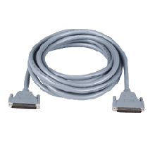 | | 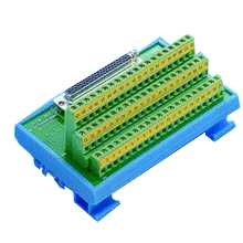 |
48-ch TTL DI/O iDAQ Module | Double-shielded cable with DB-62 connectors (1m) | Double-shielded cable with DB-62 connectors (3m) | DB62 DIN-rail Wiring Board |
| iDAQ-801 | iDAQ-731-AE16 | iDAQ-763D | iDAQ-815 |
 |  |  |  |
256kS/s/ch, 24-bit, 4-ch iDAQ Module for Sound and Vibration | Isolated DI, 16-ch Isolated DO iDAQ Module | 16-ch SSR Output iDAQ Module | 8-ch RTD Input iDAQ Module |
| iDAQ-817 | iDAQ-964 | AMAX-5580 | UNO-137 |
 |  |  |  |
200kS/s, 16-bit, 8-ch Analog Input iDAQ Module | Industrial DAQ Chassis Module for AMAX-5000 | AMAX-5580 Control IPC | V2 Small-Size Integrated DIN-Rail IPC with Intel® Atom® x6413E and x6425RE |
| PCM-24U2U3-BE 2 | PSD-A40W12 | PCL-1010B-1E | DAQNavi |
/PCM-24U2U3-BE_220190305152735.png) | /PSD-A40W12_02_S20170524163159.png) | 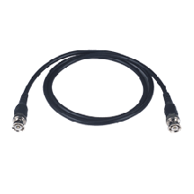 | 20231128160102.png) |
2-Port USB 3.0, mPCIe, USB-A type | DIN Rail AC to DC 100-240V 40W 12V | BNC to BNC Cable, Male (1m) | Software development kit for application development with APIs to help configure and control DAQ devices. |